Kiefner & Associates Inc.

Stress Assessment of Buried Pipes under Road Crossings or Construction Sites

Table of Contents:

  1. Analysis Approach
  2. Comparison of Kiefner Approach with API RP 1102

Introduction

All buried pipes experience loading from the weight of soil overburden. When pipelines cross railroads, roads, parking lots or construction sites, the pipes also experience live surface loading from vehicles on the ground, including heavy construction equipment in some scenarios. The surface loading results in through-wall bending in pipes, which generates both hoop stress and longitudinal stress. Current industrial standards, such as ASME B31.4 and B31.8, limit the stresses in buried pipes to maximum allowable values for hoop stress, longitudinal stress and combined biaxial stress.

API RP 1102 is one of the most widely used methods across the industry to estimate the stress in a buried pipe passing under highways or railroads. However, the application of the current API RP 1102 causes some concerns:

  • The equations were developed by Cornell University in early 1990s based on finite element analysis (FEA) and tests. Both the FEA and the tests focused on bored-installed pipes only. The resulting stress may not be conservative for pipes installed by the regular open trench method.
  • Due to the limitation of FEA results in the database used to derive the equations, the RP has applicable ranges over many parameters such as buried depth, pipe diameter over wall thickness ratio. Such limitations prevent the application of the RP to some pipes.
  • The RP only addressed pipes under highway and railroad crossings.

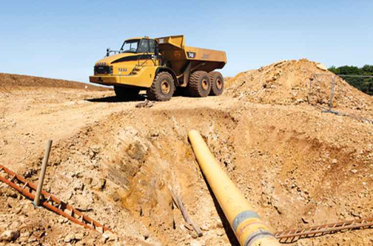
At Kiefner, we frequently help operators to assess their properties at construction sites, parking lots, farm fields, or temporary crossing by heavy equipment or vehicles where no road exists. Therefore, Kiefner has developed an independent approach to determining the stress in buried pipes under road crossings and other sites with external loading from the ground surface. The approach can be used in a broader range of scenarios and the comparison with test data from multiple groups also showed superior performance over the current API RP 1102.

Analysis Approach

Surface loading on buried pipes originates from two sources: the live load on the ground surface and the soil overburden on top of the pipe.

The live loads on the surface transfer into underground soil. The resulting pressure transferred onto the top of the buried pipe can then be calculated, such as using the Boussinesq equation. The weight of the overburden soil above the pipe also generates pressure on the pipe top. For pipe buried at shallow to moderate depth, this pressure component can be simply estimated by calculating the prism load from the weight of the soil column over the pipe. For deeper buried pipe, more rigorous models should be considered.

The total pressure on the top of the pipe is the sum of the components from both live surface load and soil overburden. This pressure results in both hoop stress and longitudinal stress in the buried pipe.

The hoop stress can be determined via CEPA[1] equation developed by Warman et al. through the modification of Spangler stress formulas. The computed hoop stress considers both the stiffening effect from internal pressure as well as the support from soil surrounding the pipes.

The longitudinal stress in the pipe resulting from surface loading has two components. The first component is due to local bending in the pipe wall. The amount of this component approximates to the Poisson ratio of pipe material multiplied by the hoop stress of local bending. The second component is due to the bending of the pipe axis under the nonuniform distribution of pressure on the pipe top in pipe axis direction. The amount of this component can be

Comparison of Kiefner Approach with API RP 1102

The analysis approach in the section above is universal. The load due to any type of vehicle or heavy equipment can be described by projecting its weight onto a grid of loading points distributed inside its footprint. The pressure on the top of the pipe can then be determined by the sum of the pressure transferring from each loading point. The approach is also flexible enough to handle the vehicle at any position and angle relative to the pipeline. The Kiefner approach does not have limitations on buried depth and pipe sizes.

Except for a more flexible application of the Kiefner approach over API RP 1102, the performance of two approaches is also compared through two plots. Experimental data are collected from three different research groups. The predicted stresses from the Kiefner approach or from API RP 1102 versus the measured stresses from the tests are plotted. One plot shows the hoop stress and the other plot shows the longitudinal stress. The red dots with cross signs are cases out of the applicable range of API RP 1102. From the plots, the Kiefner approach always predicts conservative stresses while API RP 1102 may not in many cases. Furthermore, the prediction from the Kiefner approach keeps increasing with the increase in measured stress from the tests. However, API RP 1102 sometimes predicts a different trend from that observed in the tests.

between Kiefner Approach and API RP 1102 by Hoop Stress
Plots of Comparison
between Kiefner Approach and API RP 1102 by Longitudinal Stress
Plots of Comparison

This blog post is only a brief introduction. The equations and detailed discussion of the topic can be found in a technical paper (IPC2016-64050) that Kiefner presented at the 11th International Pipeline Conference. The Kiefner approach has been implemented into a user-oriented calculator via MS Excel. The calculator is provided complimentarily during a one-day Kiefner workshop to guide pipeline engineers on how to calculate the stress in buried pipe under surface loading.

[1] Since the equations were originally developed for the Canadian Energy Pipeline Associations (CEPA).

Scroll to Top